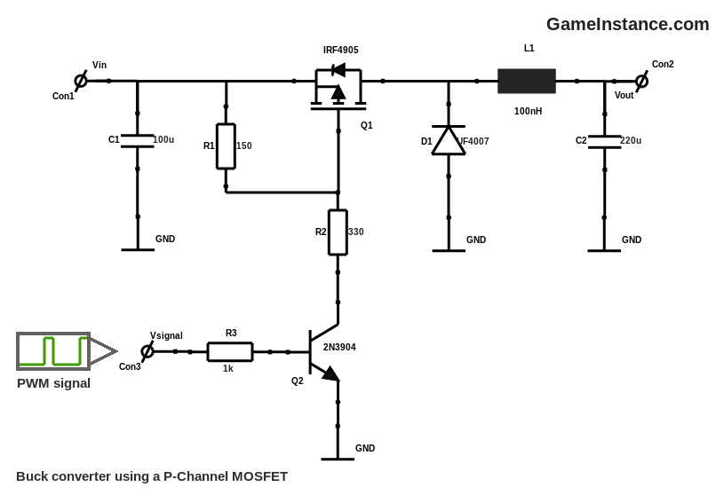
Buck Converter Circuit Diagram Using Mosfet
Buck converter circuit using ic 555 and mosfet – diy electronics projects Gameinstance.com Power electronics
Synchronous buck converter topology in its two primary states
Buck converter schematic mains voltage circuit supply power 5v circuitlab created using Analysis of four dc-dc converters in equilibrium Buck converter arduino mosfet channel using
Converter synchronous topology
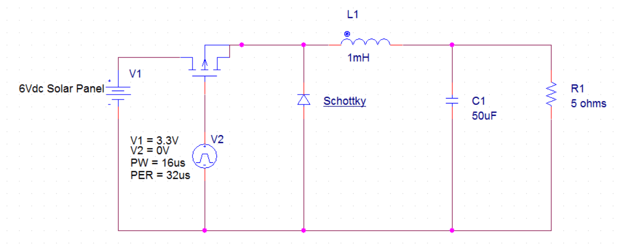
Converter buck dc circuit arduino step down voltage diagram using schematic pwm make uno use схема microcontroller circuitdigest connections перейтиWhat's the point of a mosfet in a synchronous buck converter Mosfet buck converter circuit using ic side electronics low switchConverter buck circuit using mosfet transistor ic electronics while.
Buck converter mosfet channel schematic control transistors stackBuck converter using low side n-channel mosfet Buck converter side high mosfet schematic using turn circuit circuitlab createdBuck converter circuit diagram mosfet power electronics.
Converter ne555 mosfet circuit ckt
Buck converter using ne555 and n-channel mosfetConverter buck mosfet schematic circuit using help nmos circuitlab created stack Converter buck circuit boost ac dc diagram converters working analysis equilibrium switching applications evaluation theory equivalent articles four allaboutcircuits modellingDc-dc buck converter circuit diagram.
Power supplySynchronous buck converter topology in its two primary states Buck converter synchronous mosfet diode circuit pwm fet dc electrical point element instead typical motor efficiency optimize selection current applicationsConverter mosfet circuit inductor select altium basic selecting limitation circuits.

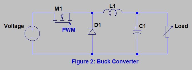
Buck converter
Buck converter circuit using ic 555 and mosfet – diy electronics projects .
.


